QAnimDrawer Help
| Index | Next |
Create a skeleton
QAnimDrawer uses a tree graph to represent a skeleton made of edges and nodes. The tree representation gives the ability to know which part depends on which node or edge (for example, when moving the knee, the foot will move along).
In order to create a skeleton, an XML file is needed.
The Tree begins with the "origin" node for which has (x,y) coordinates :
<!DOCTYPE JMskel>
<QAnimDrawer>
  <version>0.01</version>
  <skeleton>
    <origin x="0" y="-32" >
    </origin>
  </skeleton>
</QAnimDrawer>
|

|
The "origin" node has sons, which are edges :
<!DOCTYPE JMskel>
<QAnimDrawer>
  <version>0.01</version>
  <skeleton>
    <origin x="0" y="-32" >
      <sons>
        <edge z="10" name="edge1" >
          <positions>
            <pos ang="0" name="pos1" len="30" />
          </positions>
          <sons/>
        </edge>
      </sons>
    </origin>
  </skeleton>
</QAnimDrawer>
|

|
The edges have names (to help creating and debugging the XML file), and a "z" which represents the order of drawing (the biggest z will be in foreground). They can also have several positions, each of them recording an angle and a length. The position name is used for synchronizing the different parts of the skeleton.
And the edges have their edge-sons:
<!DOCTYPE JMskel>
<QAnimDrawer>
  <version>0.01</version>
  <skeleton>
    <origin x="0" y="-32" >
      <sons>
        <edge z="10" name="edge1" >
          <positions>
            <pos ang="0" name="pos1" len="30" />
          </positions>
          <sons>
            <edge z="10" name="edge2" >
              <positions>
                <pos ang="0" name="pos1" len="50" />
              </positions>
              <sons>
                <edge z="10" name="edge3" >
                  <positions>
                    <pos ang="0" name="pos1" len="20" />
                  </positions>
                  <sons>
                  </sons>
                </edge>
              </sons>
            </edge>
          </sons>
        </edge>
      </sons>
    </origin>
  </skeleton>
</QAnimDrawer>
|

|
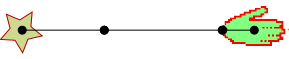
Every edge can have one image per position.
Each image has a filename "img" and "sym" (true if flipped vertically, false if not).
<!DOCTYPE JMskel>
<QAnimDrawer>
  <version>0.01</version>
  <skeleton>
    <origin x="0" y="-32" >
      <sons>
        <edge z="10" name="edge1" >
          <positions>
            <pos ang="0" name="pos1" len="30" />
          </positions>
          <sons>
            <edge z="10" name="edge2" >
              <positions>
                <pos ang="0" name="pos1" len="50" />
              </positions>
              <sons>
                <edge z="10" name="edge3" >
                  <positions>
                    <pos sym="false" ang="0" name="pos1" img="hand.png" len="20" />
                  </positions>
                  <sons>
                  </sons>
                </edge>
              </sons>
            </edge>
          </sons>
        </edge>
      </sons>
    </origin>
  </skeleton>
</QAnimDrawer>
|
|
 |
 |
Remember that each edge can have several sons, the skeleton is an n-ary tree.
 |
 |
| Index | Next |